

The Definitive Guide to Solar Panel Mounting Structures
The Definitive Guide to Solar Panel Mounting Structures: Design, Selection, Installation, and Maintenance
Chapter 1: The Unsung Hero – Understanding the Critical Role of Solar Mounting Structures
Solar panel mounting structures are fundamental to the performance, longevity, and safety of any photovoltaic (PV) system. Often overshadowed by the focus on solar panels and inverters, these support systems are the critical backbone that ensures the entire installation functions optimally and endures for its intended lifespan. The selection of an appropriate mounting structure is not merely a mechanical consideration but a strategic decision that profoundly impacts the economic and operational success of a solar energy project. These structures support the panels, enabling them to effectively absorb solar radiation while withstanding diverse environmental challenges. A comprehensive understanding of their role is therefore indispensable for manufacturers aiming to deliver robust and efficient products, and for end-users seeking to maximize their renewable energy investment.
1.1 Impact on System Efficiency: Optimal Angles and Thermal Management
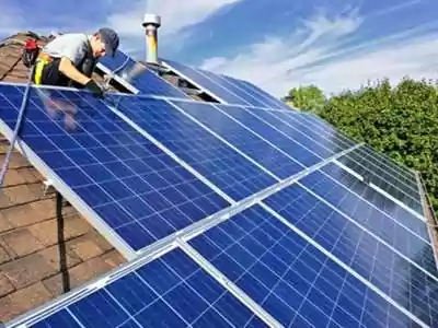
The efficiency of a solar PV system is directly influenced by the design and configuration of its mounting structure. The primary mechanism through which mounting systems affect efficiency is by enabling the optimal positioning of solar panels relative to the sun. Solar panels achieve maximum energy conversion when solar irradiance is perpendicular to their surface. Mounting structures allow panels to be installed at specific tilt and azimuth angles tailored to the geographical location and site conditions, thereby maximizing sunlight absorption throughout theday and across different seasons. For instance, ground-mounted systems generally offer greater flexibility in achieving these optimal angles compared to rooftop installations, where the existing roof geometry might impose limitations.2 The right mounting structure ensures that panels receive the maximum possible sunlight, which is crucial for overall energy production.
Beyond orientation, mounting structures play a role in thermal management. Photovoltaic panels tend to exhibit a decrease in conversion efficiency as their operating temperature increases. Properly designed mounting systems facilitate airflow around and beneath the panels, which helps to dissipate heat. Ground-mounted systems, for example, often benefit from superior airflow compared to rooftop systems where panels might be mounted closer to the roof surface, potentially leading to higher operating temperatures and reduced efficiency. The elevation and spacing provided by the mounting structure are therefore important considerations for maintaining lower panel temperatures and, consequently, higher energy yields.
The careful selection and design of a mounting structure, considering both optimal panel orientation and effective thermal management, are thus pivotal for achieving the highest possible energy output from a PV system. A system that is compromised in its positioning or heat dissipation capabilities due to a suboptimal mounting structure will inherently underperform, failing to deliver its full energy generation potential and, by extension, its expected financial returns.
1.2 Ensuring Longevity: Structural Integrity and Material Durability
Solar panel mounting structures are the primary defense for PV modules against a myriad of environmental stressors, ensuring the system’s physical survival and operational longevity over an expected lifespan of 25 years or more. The structural integrity of the mounting system is paramount. These structures must provide a stable and robust base capable of supporting the solar panels and withstanding persistent forces such as wind, snow accumulation, rain, and, in certain regions, seismic activity. A poorly designed or manufactured mounting structure, or one made from substandard materials, is susceptible to deformation, corrosion, or catastrophic failure. Such failures can lead to damage to the solar panels, the mounting structure itself, and potentially the underlying roof or property, resulting in significant repair or replacement costs and system downtime.
The durability of the materials used in the construction of mounting structures is a critical determinant of their lifespan and ability to protect the solar array. Materials must be resistant to long-term exposure to UV radiation, moisture, temperature fluctuations, and corrosive agents present in the atmosphere, such as salt spray in coastal areas or industrial pollutants. The choice between materials like aluminum, galvanized steel, or stainless steel, and the quality of any protective coatings, directly influences the structure’s resistance to degradation and its ability to maintain structural integrity over decades. Neglecting material quality can lead to premature material degradation, compromising the entire PV system’s longevity.
Therefore, a high-quality, well-engineered mounting structure is a long-term investment. While it may represent an initial cost, its contribution to the system’s durability and the avoidance of future repair expenses underscore its importance in the overall lifecycle cost of a solar installation. The structural and material robustness of the mounting system is fundamental to ensuring that the solar panels can indeed “last for decades”.
1.3 Guaranteeing Safety: Electrical, Mechanical, and Environmental Considerations
The safety of a solar PV installation is intrinsically linked to the design and quality of its mounting structure, encompassing mechanical, electrical, and environmental aspects. Mechanical safety is a primary concern, as the mounting system must securely hold solar panels, often weighing hundreds of pounds collectively, and prevent them from becoming dislodged or airborne, especially during high winds, storms, or seismic events. The engineering of these structures involves precise wind load calculations and adherence to structural codes to ensure they can withstand the maximum anticipated forces for their specific location. Failure to do so can result in property damage, injury, and significant liability.
While not directly part of the electrical circuit, mounting structures play a crucial role in electrical safety. They provide organized pathways for routing and securing electrical cables, preventing damage to wiring insulation and reducing the risk of short circuits or faults. Furthermore, metallic mounting structures must be properly grounded as part of the overall system grounding plan to protect against electrical shock hazards in the event of a fault and to provide a safe path for lightning-induced currents.A well-designed mounting system facilitates these essential electrical safety measures.
From an environmental safety perspective, certain mounting system designs can minimize impact. For instance, ballasted systems for flat roofs or ground installations avoid the need for penetrations, preserving roof membrane integrity or minimizing ground disturbance in sensitive areas. The materials used in mounting structures should also be considered for their environmental footprint, including recyclability and the energy intensity of their production.
The interconnectedness of efficiency, longevity, and safety cannot be overstated. A mounting structure that fails mechanically (a safety issue) will inevitably lead to a loss of energy production (an efficiency issue) and likely cause damage that curtails the system’s lifespan (a longevity issue). Similarly, a structure made from materials that corrode quickly (a longevity issue) can become structurally weak (a safety issue) and may shift panel orientation (an efficiency issue). This highlights the necessity of a holistic approach to mounting structure design and selection, where all three pillars are given due consideration. End-users and manufacturers alike should recognize that investing in a high-quality mounting structure is not merely an ancillary expense but a foundational requirement for a successful, reliable, and safe solar PV system that delivers on its promise for decades
Chapter 2: Navigating the Landscape – Types of Solar Panel Mounting Structures
The solar panel mounting structure market offers a diverse array of solutions tailored to different installation environments, panel types, and project objectives. Understanding these types is crucial for manufacturers to target specific market segments and for end-users to select the most appropriate system for their needs. Broadly, these structures can be categorized into rooftop-mounted, ground-mounted, and specialized systems, each with unique designs, advantages, and disadvantages.
2.1 Rooftop Mounting Systems
Pitched Roof Solutions
Pitched or sloped roofs are common in residential buildings and some commercial structures. Mounting systems for these roofs are designed to either align panels parallel to the roof surface or, if the roof’s angle is not optimal for solar collection, to provide a means of adjusting the tilt.
Railed Systems: This is the traditional and widely adopted method for pitched roofs. It involves attaching a series of parallel rails, typically made of aluminum, to the roof structure using specialized mounts or feet. Solar panels are then secured to these rails using mid-clamps (between panels) and end-clamps (at the edges of the array). Railed systems offer robust support and create a channel between the panels and the roof surface, which can be beneficial for airflow (cooling the panels) and for routing DC wiring. The structural integrity relies on secure attachment to the roof rafters and proper waterproofing at each penetration point.
Rail-Less Systems: Gaining popularity for their material and labor cost savings, rail-less systems (also known as direct-attach systems) eliminate the long rails. Instead, panels are attached directly to the roof using specialized mounting hardware, such as brackets or pucks that connect to the roof mounts. These systems can offer a more streamlined aesthetic and may allow for more flexible panel placement, potentially making more efficient use of available roof space. Examples include the EcoFasten RockIt and RibFit systems and the S-5! PVKIT for direct attachment to metal roofs.
Shared-Rail Systems: A hybrid approach, shared-rail systems reduce the total number of rails and roof penetrations required by allowing adjacent rows of solar panels to share a common, central rail. For instance, installing two rows of panels might require only three rails instead of four. This design can lead to material cost savings and faster installation times compared to traditional railed systems.
Attachments for Specific Roof Coverings: The interface between the mounting system and the roof surface is critical and varies significantly with the roofing material to ensure both structural stability and watertightness.
Tile Roofs: These require specialized tile hooks that are designed to slide under or replace existing tiles and attach securely to the roof rafters or deck without causing damage to the fragile tiles. Various hook designs exist for different tile profiles, such as Spanish (curved), Roman, clay, and flat tiles. Flashing is typically integrated with or installed around the tile hook penetration point to ensure a waterproof seal. Some systems, like Magerack’s, offer tile hooks that come with their own flashing components. Tile replacement mounts are also available, shaped like roof tiles, which can be swapped with existing tiles for easier, watertight installation.
Shingle Roofs: For asphalt shingle roofs, the most common attachment method involves L-feet (or L-brackets) that are bolted through the shingles into the roof rafters. Each L-foot penetration must be meticulously waterproofed using flashing, typically an aluminum plate slid under the shingle course above the penetration and over the course below. Sealant is often used in conjunction with the flashing for an added layer of protection. Lag bolt installation is a common technique for securing these mounts.
Metal Roofs: Mounting on metal roofs depends on the roof profile:
Standing Seam Metal Roofs: These allow for non-penetrating clamps that attach directly to the raised seams of the roof, preserving the roof’s integrity and warranty. S-5! is a well-known manufacturer of such clamps.
Trapezoidal or Corrugated Metal Roofs: These typically require penetrating brackets or L-feet that are fastened through the metal panels into the underlying structure (purlins or rafters). Self-tapping screws are often used, and it is crucial to use high-quality EPDM rubber washers or specialized sealants to ensure a watertight seal around each penetration. Mounting on the ridges (high points) of trapezoidal roofs is common to minimize wind impact and facilitate water drainage
Flat Roof Solutions
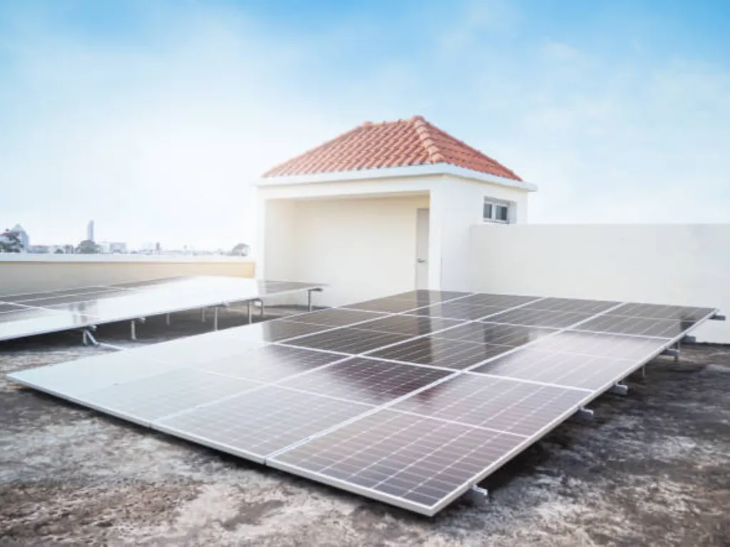
Flat roofs, common on commercial and industrial buildings, present different challenges and opportunities for solar mounting. Since the roof itself does not provide a natural tilt, mounting systems must typically elevate and angle the panels for optimal sun exposure.
Ballasted Systems: These systems are a popular non-penetrating solution for flat roofs, particularly where the roof membrane integrity is paramount or where the roof structure cannot easily accommodate numerous penetrations. The solar array is secured by placing weights, typically concrete blocks or pavers, onto trays or baskets integrated into the mounting structure. The amount of ballast required depends on wind load calculations, building height, and location. Ballasted systems are generally suitable for roofs with a slope of less than 7 degrees and add a distributed load of approximately 3-7 pounds per square foot (PSF). Building protection mats are often placed between the ballast trays and the roof membrane to prevent abrasion and protect the waterproofing. An innovative non-penetrating system, Solar Stack, uses a spray polyurethane foam adhesive to bond mounts to the roof surface, eliminating the need for ballast or mechanical penetrations.
Penetrating (Mechanically Attached) Systems: These systems involve anchoring the mounting structure directly to the building’s structural members through the roof membrane. This method provides high stability and is often preferred in areas with very high wind loads or seismic considerations where ballasted systems might not be sufficient. Proper flashing and sealing of each penetration are critical to prevent leaks and maintain the roof’s warranty. These systems can offer a lower profile compared to some tilted ballasted systems, potentially reducing wind resistance.
Hybrid Systems: Combining elements of both ballasted and penetrating systems, hybrid mounts offer a balance of features. They might use fewer penetrations than fully attached systems, supplemented by some ballast, or vice-versa, providing versatility for various roof conditions and load requirements.
Tilted Mounting Systems (General): Regardless of whether they are ballasted or attached, systems on flat roofs typically incorporate a tilt mechanism to angle the panels towards the sun, usually between 5 and 35 degrees, or even up to 45 degrees with some designs. This tilt increases energy capture compared to panels laid flat. Adjustable leg systems allow for setting specific tilt angles.
East-West Systems: A specific configuration for flat roofs, often using ballasted tilted structures, where panels are oriented in an east-west direction in a “tent-like” or “sawtooth” arrangement. This layout can maximize panel density on the roof and provide a more distributed power generation curve throughout the day, with peaks in the morning and afternoon, as opposed to a single midday peak for south-facing arrays. SIC Solar offers an East-West Solar Ballasted Mounting System.
The choice of a flat roof mounting system involves careful consideration of the roof’s structural capacity, membrane type and warranty, local wind and snow loads, seismic conditions, and project economics.
Ground-Mounted Systems
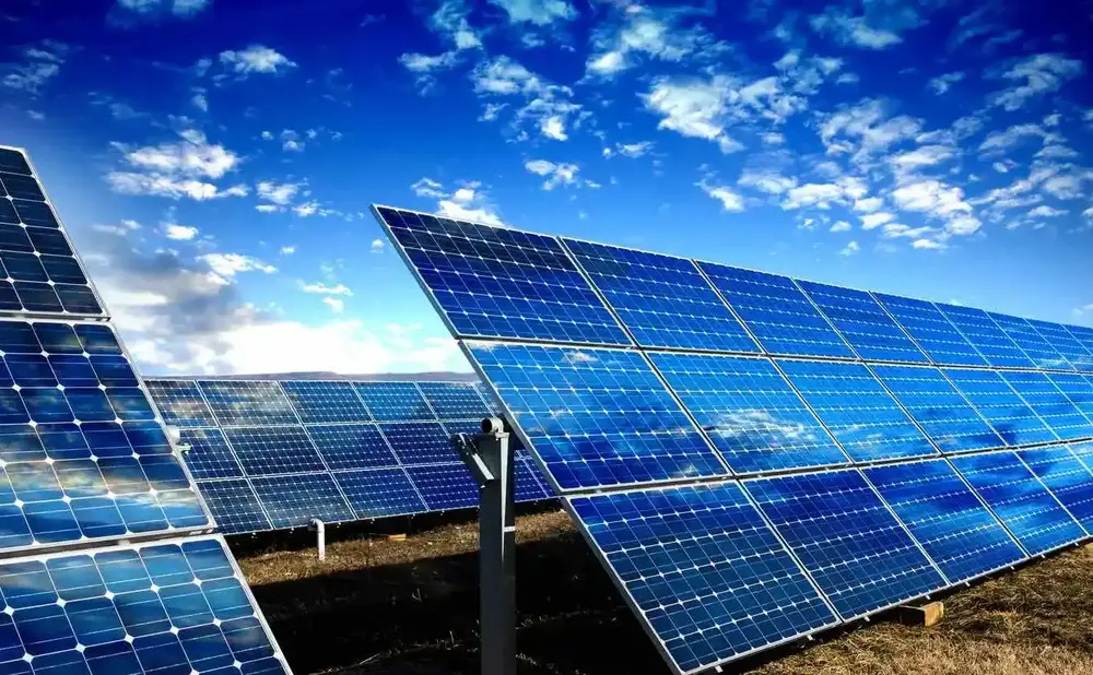
Ground-mounted solar systems are installed on open land, offering significant advantages in terms of scalability, optimal orientation, and ease of maintenance. They are commonly used for utility-scale solar farms but are also viable for residential and commercial properties with sufficient available space.
2.2.1 Fixed-Tilt Structures
Fixed-tilt ground mounts secure panels at a predetermined, non-adjustable angle and azimuth, typically optimized for the site’s latitude and to maximize annual energy production. They are generally simpler in design, lower in initial cost, and require less maintenance compared to tracking systems due to the absence of moving parts.
Single-Pole Mounts: These systems elevate a small number of panels (typically 1 to 4, or more for larger poles) on a single, robust pole that is anchored into the ground. They are useful when a higher elevation is needed to avoid ground-level obstructions or snow accumulation, or for smaller, distributed installations. Pole mounts can sometimes incorporate manual tilt adjustment or even small tracking systems.
Dual-Pole (and Multi-Pole) Mounts: More common for larger fixed-tilt arrays, these systems use two or more posts per section of racking to support rows of solar panels. The racking structure typically consists of vertical posts, horizontal beams or purlins, and rails to which the panels are clamped. Foundations can be driven piles, ground screws, or concrete footings.
2.2.2 Adjustable-Tilt and Tracking Systems
To enhance energy capture, some ground-mounted systems incorporate mechanisms to adjust the panel orientation relative to the sun. These systems can significantly increase energy yield, often by 15% to over 45%, depending on the technology and location, but they also introduce higher initial costs, complexity, and maintenance requirements.
Manual Adjustable Tilt: These systems allow the tilt angle of the panels to be changed manually, typically on a seasonal basis (e.g., steeper tilt in winter, shallower in summer) to optimize for the sun’s varying path. This offers a performance boost over fixed-tilt systems at a lower cost and complexity than automated trackers, but it requires manual labor for adjustments.
Single-Axis Trackers: These automated systems track the sun’s movement along a single axis, most commonly from east to west throughout the day. They can increase energy production by approximately 15-35% compared to fixed-tilt systems. Single-axis trackers are widely used in utility-scale projects and offer a good balance between increased energy yield and system cost/complexity. Variations include Horizontal Single-Axis Trackers (HSAT), Vertical Single-Axis Trackers (VSAT), and Tilted Single-Axis Trackers (TSAT or HTSAT), where the axis of rotation itself is tilted.
Dual-Axis Trackers: These systems track the sun on two axes, continuously adjusting both the east-west orientation and the north-south tilt to keep the panels perpendicular to the sun’s rays at all times. They offer the highest potential energy gain (up to 40-50% or more over fixed-tilt) but are also the most complex, expensive, and maintenance-intensive type of tracking system. Due to their cost and complexity, they are less common than single-axis trackers, often found in specific applications where maximizing output per panel is critical or in smaller residential/commercial setups where land is extremely limited.
2.2.3 Foundation Options for Ground-Mounted Systems
The foundation is a critical element of any ground-mounted system, providing stability and transferring loads to the ground. The choice of foundation is heavily influenced by soil conditions, local climate (frost depth, wind loads), project scale, and cost.
Driven/Rammed Piles: Steel posts, such as I-beams, C-channels, or H-piles, are driven or vibrated directly into the ground using specialized machinery. This method is common for large-scale utility projects where soil conditions are favorable (e.g., good cohesion, limited rocks or refusal) due to its speed and cost-effectiveness. However, installation can be noisy and challenging in rocky terrain. Ramming piles, often C-shaped, may offer less grip and wind resistance compared to ground screws in some soil types.
Ground Screws (Helical Piles/Screw Piles): These are large, galvanized steel screws or piles with helical blades that are rotated into the ground using hydraulic equipment. They are versatile and suitable for a wide range of soil conditions, including sandy soils, areas with high water tables, or moderately rocky ground. Ground screws cause minimal soil disturbance, can be installed quickly, and are often removable and reusable. They generally offer excellent grip and resistance to uplift and lateral forces.
Concrete Piers/Pads/Footings: This traditional method involves excavating holes and pouring concrete to create individual piers or continuous footings, often with embedded steel posts or anchor bolts. Concrete foundations are very stable and durable but are more labor-intensive and time-consuming due to excavation, formwork, concrete pouring, and curing time. They are often used for smaller installations or where soil conditions are unsuitable for driven piles or screws.
Ballasted Foundations (Ground): Similar to flat roof ballasted systems, these use concrete blocks or other heavy materials to secure the array on the ground without ground penetration. They are ideal for sites where excavation is prohibited or difficult, such as landfills, brownfields, or environmentally sensitive areas. Ballasted systems typically require a larger surface area to distribute the weight and ensure stability against wind uplift and sliding. Installation is generally quick and involves minimal site disruption.
A thorough geotechnical investigation is crucial before selecting and designing the foundation for any ground-mounted solar project to ensure long-term stability and performance.
Specialized Mounting Structures
Beyond standard rooftop and ground-mounted systems, a range of specialized mounting structures has emerged to meet unique application requirements, optimize land use, or integrate solar technology more seamlessly into the built environment.
Solar Carports and Canopies: These structures serve a dual purpose: providing shelter for vehicles (or other areas) while simultaneously generating solar electricity. Commonly found in commercial, institutional (e.g., schools), and large residential parking lots, solar carports can be designed to cover single or multiple rows of parking spaces. Materials typically include high-strength aluminum alloy or carbon steel for the support structure. Design considerations include foundation depth (often 1.5-2 meters), wind load resistance (up to 150 km/h in coastal areas), panel weight distribution, vehicle clearance height, and water management (e.g., waterproof decking or gutter systems). Many solar carports are now being integrated with electric vehicle (EV) charging stations. Grace Solar and Grengy are examples of companies offering various solar carport solutions, including waterproof designs.
Building Integrated Photovoltaics (BIPV): BIPV involves replacing conventional building materials with PV-generating components, making the solar technology an integral part of the building’s envelope. Examples include PV roofing tiles or shingles, solar facades (replacing glass or cladding), and PV skylights or windows. BIPV offers excellent aesthetic integration and can reduce overall building material costs, but it often involves higher upfront costs for the PV components and more complex design and installation compared to traditional Building Applied Photovoltaics (BAPV). Technical challenges include electrical design integration and ensuring the BIPV components meet all building code requirements for weatherproofing, fire resistance, and structural performance.
Floating Solar Systems (Floatovoltaics): This innovative approach involves deploying solar panels on buoyant structures anchored in bodies of water such as lakes, reservoirs, irrigation canals, or even calm offshore locations. Key advantages include land conservation, reduced water evaporation from the covered surface, and potentially increased panel efficiency due to the cooling effect of the water. However, floatovoltaics present unique challenges, including the need for robust and corrosion-resistant floating platforms, specialized anchoring and mooring systems to withstand wind, waves, currents, and water level fluctuations, and durable, waterproof electrical cabling solutions. Installation and maintenance can also be more complex and costly than land-based systems.
Wall-Mounted Systems: Solar panels can be installed directly onto the vertical facades of buildings. This is particularly useful in dense urban environments where roof and ground space are limited, or for specific architectural designs. Wall-mounted panels can be fixed parallel to the wall or tilted for better solar exposure. While they can contribute to a building’s energy supply and even act as an additional insulation layer reducing cooling costs , their energy yield is often lower than optimally tilted rooftop or ground-mounted systems due to non-ideal orientation and potential shading from surrounding structures. Specialized strong brackets and anchors are required for secure facade attachment. The RAULI WALL system, for instance, uses high-strength Nordic steel and an “EASY SLIDE” installation method for facade applications.
Agrivoltaics Mounting Solutions: These systems are designed to enable the dual use of land for both solar energy generation and agriculture. This typically involves elevating the solar panels higher off the ground or increasing the spacing between panel rows to allow sufficient sunlight for crops to grow underneath and to permit access for farming equipment or livestock grazing. Agrivoltaics can address concerns about land-use conflicts, provide economic benefits to farmers, and potentially improve crop yields or animal welfare due to shading and reduced water stress. However, these systems can have higher construction costs and require careful planning regarding panel height, spacing, crop selection, and equipment compatibility.
The landscape of solar mounting structures is clearly evolving beyond simple support functions. There is a discernible trend towards systems that offer enhanced aesthetics, dual-purpose functionality (like carports providing shelter or BIPV replacing building materials), and solutions for challenging or previously unusable spaces (like water bodies for floatovoltaics or vertical facades for wall mounts). This convergence of functionality with other benefits such as architectural integration or optimized land use indicates a maturing market catering to more diverse end-user needs. Manufacturers are responding with innovative designs and materials, while end-users, particularly in commercial and urban settings, are increasingly seeking solutions that offer more than just kilowatt-hours.
For ground-mounted systems, the foundation remains a pivotal and often complex aspect. The choice between driven piles, ground screws, concrete footings, or ballasted systems is not arbitrary but is critically dependent on detailed site-specific geotechnical assessments. This dependency significantly influences project costs, installation timelines, and the degree of environmental disturbance. Consequently, manufacturers must offer versatile systems adaptable to various foundation interfaces, or provide specialized foundation-integrated solutions. End-users and developers, in turn, must recognize that upfront investment in thorough site investigations is crucial to prevent costly errors in foundation selection, which could lead to under-engineered systems prone to failure or over-engineered systems incurring unnecessary expenses.
Another significant trend is the increasing demand for non-penetrating mounting solutions, particularly for flat roofs and certain types of metal roofs. Ballasted systems for flat roofs and specialized clamps for standing seam metal roofs are prime examples, driven by the desire to preserve roof membrane integrity, avoid leaks, and maintain roof warranties. This presents a considerable market opportunity for manufacturers to develop and refine reliable, cost-effective, and code-compliant non-penetrating technologies that are easy to install.
Finally, solar trackers represent a persistent trade-off in the mounting structure domain. While consistently delivering higher energy yields compared to fixed-tilt systems, they come with a higher price tag, increased mechanical complexity, and more demanding maintenance schedules. The economic and operational viability of trackers is therefore highly sensitive to project scale, site irradiance levels, electricity prices, and the operator’s capacity for ongoing maintenance. For large utility-scale projects in high-insolation areas, the increased yield often justifies the added investment, but for smaller residential or some commercial applications, the lifecycle costs and complexity may outweigh the benefits.
The following table provides a comparative overview of the primary solar panel mounting structure types:
Table 2.1: Comparative Overview of Solar Panel Mounting Structure Types
| Mounting Type | Sub-Type / Foundation | Typical Materials | Key Advantages | Key Disadvantages | Typical Applications | Relative Cost |
| Rooftop – Pitched | Railed | Aluminum, Stainless Steel | Robust, good airflow, wiring channel | More components, potentially higher labor than rail-less | Residential, Commercial | Medium |
| Rail-Less | Aluminum, Specialized Hardware | Fewer materials, potentially faster install, aesthetic | May have limitations on some roof types/loads | Residential, Commercial | Medium-Low | |
| Shared-Rail | Aluminum | Fewer penetrations, material savings | Design complexity might be slightly higher | Residential, Commercial | Medium-Low | |
| – Tile Attachment | Stainless Steel/Aluminum Hooks, Flashing | Secure on tiles, preserves tile integrity | Installation can be slower, risk of tile breakage if not careful | Residential (Tile Roofs) | Medium-High | |
| – Shingle Attachment | Aluminum L-feet, Flashing | Standard, reliable, good waterproofing with proper flashing | Requires careful sealing of penetrations | Residential (Shingle Roofs) | Medium | |
| – Metal Roof Attachment | Aluminum/SS Clamps (Standing Seam), Brackets (Trapezoidal) | Non-penetrating for standing seam ; secure for trapezoidal | Penetrating types need careful sealing; clamps specific to seam type | Residential, Commercial (Metal Roofs) | Medium | |
| Rooftop – Flat | Ballasted | Aluminum, Steel, Concrete Ballast | No roof penetrations, preserves warranty, quick install | Adds significant weight, needs structural assessment, may not suit high wind/seismic zones 25 | Commercial, Industrial (Flat Roofs) | Medium |
| Penetrating (Attached) | Aluminum, Steel | High stability, lower profile | Requires roof penetrations, risk to warranty if not sealed perfectly | Commercial, Industrial (Flat Roofs) | Medium-High | |
| Hybrid | Mixed | Versatile, balanced stability/penetration risk | Can be more complex to design/install | Commercial, Industrial (Flat Roofs) | Medium-High | |
| East-West | Aluminum, Steel, Concrete Ballast | Maximizes panel density, smoother power curve | Typically lower individual panel tilt, specific orientation | Commercial, Industrial (Flat Roofs) | Medium | |
| Ground-Mounted – Fixed-Tilt | Single-Pole | Steel, Aluminum | Small footprint, elevation over obstructions | Limited panel capacity per pole, foundation depth can be significant | Residential, Small Commercial, Agricultural (spot use) | Medium-High |
| Dual/Multi-Pole (Piles/Screws) | Galvanized Steel, Aluminum | Scalable, optimal fixed orientation possible, robust | Requires land, foundation cost varies with soil | Utility, Commercial, Agricultural, Residential (large lots) | Medium | |
| Dual/Multi-Pole (Concrete) | Galvanized Steel, Aluminum, Concrete | Very stable, adaptable to poor soil for piles | Labor-intensive, cure time, higher material cost for concrete | Utility, Commercial, Agricultural, Residential | Medium-High | |
| Ballasted (Ground) | Steel, Aluminum, Concrete Ballast | No ground penetration, good for sensitive sites/landfills | Requires more space, heavy, wind limitations | Landfills, Brownfields, Sensitive Sites | Medium-High | |
| Ground-Mounted – Tracker | Manual Adjustable Tilt | Steel, Aluminum | Higher yield than fixed, lower cost than auto-trackers | Requires manual labor for adjustment, yield gain less than auto | Residential, Small Commercial, Agricultural | Medium |
| Single-Axis Tracker | Steel, Aluminum | Significant yield increase (15-35%), good cost-benefit for large scale | Higher cost, more maintenance, moving parts, needs space | Utility, Large Commercial, Agricultural | High | |
| Dual-Axis Tracker | Steel, Aluminum | Maximum yield increase (up to 40%+), precise tracking | Highest cost, most complex, highest maintenance, larger footprint per unit | Niche Utility, Research, High-Value Land | Very High | |
| Specialized Structures | Solar Carport/Canopy | Steel, Aluminum | Dual-use (shelter & power), EV charging integration | Higher structural cost than simple ground-mount, site specific design | Commercial, Institutional, Residential Complexes | High |
| BIPV | Specialized PV Glass, Tiles, Facades | Aesthetic integration, replaces building materials | High cost, complex installation, potentially lower efficiency than dedicated panels | Architectural Buildings (New/Retrofit) | Very High | |
| Floating Solar (Floatovoltaics) | HDPE Floats, Aluminum/Steel Frames | Land conservation, water cooling benefit, reduced evaporation | Specialized anchoring/mooring, complex O&M, higher cost, environmental impact study needed | Reservoirs, Lakes, Water Treatment Ponds | High | |
| Wall-Mounted | Aluminum, Steel, Specialized Brackets | Utilizes vertical space, architectural element, potential insulation benefit | Often suboptimal orientation/shading, lower yield, specialized anchors needed | Urban Buildings, Facades, Retrofits | Medium-High | |
| Agrivoltaics | Steel, Aluminum (often elevated) | Dual land use (farming & solar), potential crop benefits | Higher mounting cost, design complexity for light & access | Agricultural Land | High |
Note: Relative Cost is a general indication and can vary significantly based on project size, location, materials, and specific design requirements.
2.4 The Interplay of Functionality, Aesthetics, and Site Constraints
The expanding variety of solar mounting structures reflects a broader industry trend: the increasing importance of integrating solar technology in ways that are not only functional but also aesthetically considerate and adaptable to diverse site constraints. While utility-scale ground-mounted systems might prioritize raw efficiency and cost per watt, urban, commercial, and residential applications often demand more nuanced solutions.
Aesthetic Integration and Dual Functionality:
Building Integrated Photovoltaics (BIPV) are at the forefront of aesthetic integration, where solar cells become indistinguishable from conventional building materials like roofing tiles, facade elements, or glazing.4 This approach is particularly appealing for architecturally sensitive projects or new constructions where the solar array is envisioned as part of the building’s design language from the outset. Similarly, solar carports and canopies transform parking areas or walkways into power-generating assets while providing valuable shade and weather protection.4 Some modern wall-mounted systems, like the RAULI WALL, are also designed with architectural elegance in mind, offering customizable colors and sleek profiles.77 Agrivoltaic systems address land-use concerns by enabling simultaneous agricultural production and energy generation, showcasing a functional synergy that can also enhance community acceptance of solar projects.63 This drive towards dual functionality and improved aesthetics suggests that manufacturers must increasingly consider design versatility and integration capabilities beyond basic structural support.
Addressing Site-Specific Challenges:
The choice of mounting system is heavily dictated by the specific characteristics of the installation site. For ground-mounted systems, geotechnical conditions are a primary driver for foundation selection.6 Driven piles might be cost-effective in suitable soils, but rocky terrain or environmentally sensitive sites may necessitate ground screws or ballasted foundations, each with distinct cost, labor, and environmental implications.24 This underscores the critical need for thorough site assessments before system selection.
For rooftop installations, particularly on flat roofs, the desire to avoid penetrations to maintain roof integrity and warranties has spurred innovation in non-penetrating solutions. Ballasted systems are a common choice, but their applicability depends on the roof’s load-bearing capacity. Adhesive-based systems like Solar Stack offer an alternative by bonding directly to the roof surface. For pitched metal roofs, non-penetrating standing seam clamps are preferred where possible. These trends highlight a significant market focus on solutions that are both effective and minimally invasive.
The increasing sophistication of mounting structures, from AI-enhanced trackers to specialized systems for challenging environments, demonstrates that the “one-size-fits-all” approach is no longer sufficient. Both manufacturers and end-users must navigate this complex landscape, balancing performance requirements with aesthetic considerations, site limitations, and lifecycle costs to arrive at the optimal mounting solution.
Chapter 3: Deconstructing the System – Key Components and Materials
A solar panel mounting system, whether for a rooftop, ground, or specialized application, is an assembly of various components meticulously designed to work in concert. The choice of materials for these components is equally critical, dictating the system’s strength, durability, weight, corrosion resistance, and overall cost. Understanding these elements is vital for manufacturers in their design and sourcing processes, and for end-users in assessing the quality and long-term viability of an installation.
3.1 Essential Components of Solar Mounting Structures
While designs vary widely, most solar racking solutions incorporate several fundamental components that ensure the solar panels are securely affixed and optimally positioned.
Profiles/Rails: These are the primary structural members, typically long extruded aluminum or steel sections, onto which solar panels are attached. Rails provide the necessary support to span between attachment points on a roof or foundation. Their design often includes channels or slots for attaching clamps and managing wiring. The strength of the rail and its ability to span certain distances without excessive deflection are key design parameters; for example, Magerack rails are noted to support spans up to 8 feet. Eurotec offers various installation profiles tailored for pitched roofs, trapezoidal sheets, and flat roofs.
Clamps (Mid and End): Clamps are used to secure the solar panels to the rails. Mid-clamps are positioned between adjacent panels, gripping the frames of two panels simultaneously. End-clamps are used at the extremities of a panel row to secure the outermost panels. Many modern clamps are designed for ease of installation, featuring top-down tightening bolts and, in some cases, integrated bonding capabilities that electrically connect the panel frame to the rail, simplifying grounding requirements. Clamp designs must be compatible with the thickness of the solar panel frames.
Fasteners (Bolts, Nuts, Screws, Washers): A wide variety of fasteners are essential for assembling the mounting structure itself and for attaching it to the underlying surface (roof or foundation). The quality, material, and proper tightening (torque) of these fasteners are critical for the system’s long-term structural integrity and to prevent loosening due to vibration or thermal cycling. Common types include:
- Hanger bolts: Used for attaching to wooden roof rafters, often through tile or metal roofing.
- Lag screws/bolts: Also for wood attachment, common for shingle roof mounts.
- Expansion bolts: For securing mounts into concrete foundations or roofs.
- Self-tapping screws: Used for attaching to metal roofing or thin steel members, often with EPDM sealing washers.
- T-bolts and Rail Fasteners: Specialized bolts that slide into rail channels for attaching clamps or other components.
- U-bolts: For clamping around pipes or poles.
- Hex head bolts with lock nuts and spring washers: Provide secure connections for structural components, resisting loosening.
- Flange nuts with serrations: Offer self-locking properties. The choice of fastener material (e.g., stainless steel, coated galvanized steel) is crucial for corrosion resistance.
Mounts/Feet/Roof Attachments: These components form the direct interface between the racking system and the roof structure or ground foundation.
- L-feet (L-brackets): Commonly used on shingle roofs, bolted to rafters and providing a mounting point for rails. Often paired with flashing.
- Tile Hooks: Specialized hooks designed for various tile roof profiles (flat, curved, Spanish) that attach to rafters or deck, typically under the tiles to maintain waterproofing.
- Standoffs: Posts that elevate the racking system further from the roof surface, used for various roof types, especially where clearance is needed for airflow, obstacles, or on new roofs. They often come with L-brackets for rail attachment and require robust waterproofing.
Flashing: An indispensable component for any rooftop installation that involves penetrations. Flashing consists of thin pieces of metal (commonly aluminum) or specialized EPDM/sealant systems, designed to be integrated with the roofing material (e.g., slid under shingles) to create a watertight barrier around each penetration point, preventing leaks. Magerack, for example, offers a patented L-foot with a one-piece aluminum flashing designed for absolute waterproofing.
Connectors (Splices, Angle Connectors, T-Connectors): Used to join sections of rails to achieve longer lengths or to create specific angles and connections within the framework. Rail splices can also provide electrical bonding between rail sections. Eurotec provides corner and T-connectors for flat roof systems.
Grounding Lugs/Clips: Essential for electrical safety, these components are used to bond all metallic parts of the mounting structure and panel frames to the system’s grounding conductor, providing a safe path for fault currents. They can be attached directly to rails or other structural members. Specific torque values are often required for grounding connections.
The interplay of these components, their material composition, and their correct assembly are all critical to the overall performance and safety of the solar mounting structure.
3.2 Material Science for Mounting Structures
The selection of materials for solar mounting structures is a crucial decision that balances structural performance, durability, weight, corrosion resistance, and cost over the system’s multi-decade lifespan. The primary materials used are aluminum alloys and various types of steel, with emerging interest in composites and polymers.
3.2.1 Aluminum Alloys
Aluminum is a widely favored material for solar mounting structures due to its advantageous combination of being lightweight, possessing good strength-to-weight ratio, and exhibiting excellent natural corrosion resistance. When exposed to air, aluminum forms a passive, protective layer of aluminum oxide on its surface, which inhibits further corrosion. This makes it particularly suitable for rooftop applications where minimizing additional load is important, and in many outdoor environments.
Common Alloys and Tempers:
- 6005 Aluminum Alloy: This alloy is often cited as a preferred choice for solar mounting components, offering a good balance of mechanical strength, formability, weldability, and corrosion resistance. It is stronger than 6063 and possesses good corrosion resistance, making it a versatile option. Solaracks, for example, utilizes 6005 T5 aluminum for its mounting kits.
- 6061 Aluminum Alloy: Known for its high strength, excellent machinability, and weldability, 6061 is frequently used in more demanding structural applications where higher mechanical properties are required to withstand significant wind or snow loads.
- 6063 Aluminum Alloy: This alloy is valued for its excellent surface finish, good formability, and superior corrosion resistance, though it has moderate strength compared to 6005 and 6061.It is often used in architectural applications and for lightweight structures.
- Temper (T5, T6): The temper designation (e.g., T5, T6) indicates the heat treatment process the aluminum has undergone, which significantly affects its final hardness, strength, and ductility.For solar panel frames, a hardness of over 12HW is often specified. Vishakha Renewables specifies T5-T6 temper for their 6063 and 6005 alloy frames.
Manufacturing and Finishing:
- Extrusion: Aluminum profiles for rails and frames are typically manufactured through an extrusion process, where heated aluminum billets are forced through a die of the desired cross-sectional shape.1 Control of extrusion temperature and speed is critical.
- Anodizing: To further enhance corrosion and wear resistance, aluminum components are often anodized. This electrochemical process thickens the natural protective oxide layer. For solar applications, an anodizing layer thickness of 15 micrometers (μm) or more is commonly specified, compared to about 10μm for ordinary aluminum profiles. Anodizing can also provide different color finishes, such as silver or black.
- Powder Coating: As an alternative or supplement to anodizing, powder coating can be applied to aluminum structures. This involves applying a dry powder electrostatically and then curing it under heat to form a durable, protective, and often colored finish. It offers good corrosion and UV resistance.
The specific chemical composition of the aluminum alloy, particularly the content of elements like Silicon (Si), Magnesium (Mg), and Iron (Fe), is strictly controlled to achieve the desired mechanical properties and corrosion resistance.105 For instance, typical specifications might require Si 0.38-0.42%, Mg 0.53-0.57%, and Fe <0.18%.
3.2.2 Steel Solutions
Steel is another primary material for solar mounting structures, valued for its high strength, rigidity, and often lower initial material cost compared to aluminum, especially for large-scale ground-mounted projects. However, steel is inherently susceptible to corrosion (rusting) and therefore requires robust protective coatings.
Galvanized Steel: This is the most common form of steel used for solar racking. Galvanization involves applying a protective zinc coating to the steel surface to prevent corrosion.
- Hot-Dip Galvanizing (HDG): This process involves immersing the fabricated steel components in a bath of molten zinc (or a zinc alloy). This creates a metallurgically bonded coating that is highly durable and provides excellent corrosion protection, including sacrificial protection where the zinc corrodes preferentially to the steel if the coating is scratched. HDG steel is widely used for ground-mount posts, frames, and other structural components. Common standards governing HDG include ASTM A123/A123M (for general iron and steel products) and ISO 1461. Typical galvanized coating thickness for solar applications ranges from 70 to 100 μm.
- Pre-Galvanizing: Steel sheet or coil is galvanized in a continuous process before fabrication. While offering some protection, cut edges and weld areas may be less protected than with post-fabrication HDG.
- Electro-Galvanizing: A thinner zinc coating is applied electrolytically. This offers less corrosion protection than HDG and is generally not suitable for long-term outdoor exposure in demanding environments.
- Advanced Zinc Coatings: Modern galvanized steels may feature alloyed zinc coatings for enhanced performance. These include:
- Zinc-Aluminum (ZA, Galfan): Offers improved corrosion resistance compared to pure zinc in some environments.
- Zinc-Magnesium (ZM) / Zinc-Aluminum-Magnesium (ZAM): These coatings provide significantly enhanced corrosion protection, especially in chloride-rich (e.g., coastal) or high-humidity environments. Steel grade S450GD with a +ZM coating, for example, offers extended protection in maritime zones. ZAM275 is mentioned as a material for waterproof rails.
- Aluminum-Zinc (AZ, Galvalume): Combines aluminum’s barrier protection with zinc’s sacrificial protection, offering good corrosion and heat resistance.
- Steel Grades: Various structural steel grades are used, such as Q235, Q355, Q420 (Chinese standards), S275, S355 (European standards), and S450GD (high-strength structural steel). The choice depends on the required strength and load-bearing capacity.
Cold-Formed Steel: Steel profiles (e.g., C-channels, Z-purlins) are often manufactured by cold-forming (bending or rolling steel sheet or strip at room temperature). These components can then be galvanized.
Stainless Steel: Offering the highest level of corrosion resistance, stainless steel is an excellent but more expensive option, particularly for installations in extremely harsh environments such as coastal/marine locations or areas with high industrial pollution.
- Grade 304 Stainless Steel: A common austenitic grade providing good general corrosion resistance. It is suitable for many atmospheric conditions but can be susceptible to chloride-induced pitting and crevice corrosion. It is generally more affordable than Grade 316.
- Grade 316 Stainless Steel: Also an austenitic grade, but with the addition of molybdenum (typically 2-3%). Molybdenum significantly enhances its resistance to pitting and crevice corrosion, especially in chloride-containing environments (e.g., saltwater, de-icing salts). This makes Grade 316 the preferred choice for marine and aggressive industrial applications, despite its higher cost. Stainless steel components, especially fasteners, are often used even in aluminum or galvanized steel structures due to their superior corrosion resistance at critical connection points.
3.2.3 Fasteners: Material, Strength, and Corrosion Protection
Fasteners (bolts, screws, nuts, washers) are the linchpins of any mounting structure, and their failure can compromise the entire system.
- Materials: Stainless steel (often 304 or 316 for corrosion resistance) and high-strength carbon steel with protective coatings are common.
- Strength Grades: For steel bolts, strength grades such as 8.8, 10.9, and 12.9 (ISO standards) indicate their mechanical properties (tensile and yield strength) and ability to withstand high loads and stresses.
- Corrosion Protection: This is critical, especially since fasteners often create crevices where moisture can accumulate. Coatings for steel fasteners include hot-dip galvanizing, mechanical galvanizing, or specialized proprietary coatings like zinc-nickel alloys. Stainless steel fasteners offer inherent corrosion resistance.
The selection of appropriate fasteners with adequate strength and corrosion protection for the specific application and environment is essential for the long-term reliability of the mounting structure.
3.2.4 Emerging and Innovative Materials
While aluminum and steel dominate the market, research and development continue into alternative materials that offer unique advantages.
Composites (Fiber-Reinforced Polymers – FRP): These materials, such as glass fiber reinforced polymer (GFRP) or carbon fiber reinforced polymer (CFRP), are gaining attention for their potential benefits, including being lightweight, inherently corrosion-proof, and having high strength-to-weight ratios.
- Polyurethane (PU) Composites: Covestro, for example, has developed PU composite solar panel frames that reportedly exhibit axial tensile strength more than 7 times that of typical aluminum alloy, along with strong salt mist (IEC 61701) and ammonia (IEC 62716) corrosion resistance. Their high volume resistivity can also help reduce Potential-Induced Degradation (PID) in solar panels.
- FRPs can offer design flexibility and a long service life with reduced maintenance needs. However, historically, higher initial costs, lower production speeds for some types (especially CFRPs), and limited long-term field data have been barriers to widespread adoption compared to traditional metals. The economic viability often depends on lifecycle cost advantages in specific applications, such as highly corrosive environments or weight-sensitive installations.
Thermally Conductive Polymers: Senergy Innovations is developing patent-pending thermally conductive polymers designed for heat management in solar and other energy applications. These materials aim to offer thermal conductivity comparable to metals, along with benefits like scalability (through injection molding, extrusion), flexibility, durability, and corrosion resistance.
Spray Polyurethane Foam Adhesive: Used in innovative non-invasive mounting systems like Solar Stack, this material allows solar mounts to be securely bonded to roof surfaces without any mechanical penetrations, thereby eliminating leak risks associated with drilling. This approach focuses on the attachment method rather than the primary structural material of the racking itself, which could still be aluminum or steel.
The material selection process is evidently a complex optimization. It’s not merely about choosing the strongest or cheapest material, but about finding the optimal balance of mechanical properties, corrosion resistance tailored to the specific installation environment, weight considerations (especially for rooftops), ease of fabrication and installation, projected lifespan, and overall lifecycle cost. For carbon steel structures, the quality and type of galvanization and any additional protective coatings are as crucial as the base steel itself, profoundly impacting longevity, particularly in corrosive settings. Furthermore, the fasteners, though small, are critical; their material, strength, and corrosion protection must match the demands of the system, as overlooking their quality can jeopardize the entire structure. While innovative materials like composites and advanced polymers show promise with benefits such as being lightweight and corrosion-proof, their broader market adoption is often tempered by higher initial costs and the need to demonstrate clear lifecycle advantages over well-established aluminum and steel solutions.
Table 3.1: Material Properties and Applications for Solar Mounting Structures
| Material Type | Key Properties (Typical Ranges/Examples) | Typical Coating/Treatment | Advantages | Disadvantages | Common Applications | Relative Cost Index | Expected Lifespan (Years) |
| Aluminum Alloy (e.g., 6005-T5) | Tensile: ~260-310 MPa; Yield: ~240-270 MPa; Density: ~2.7 g/cm³; Good natural corrosion resistance | Anodizing (e.g., 15µm), Powder Coating | Lightweight, good strength-to-weight, excellent corrosion resistance in many environments, recyclable, easy to fabricate | Higher initial cost than some steels, lower strength than steel, potential for galvanic corrosion with dissimilar metals | Rooftop (pitched & flat), Ground-mount (fixed & tracker), Carports | Medium-High | 25+ |
| Aluminum Alloy (e.g., 6061-T6) | Tensile: ~290-310 MPa; Yield: ~240-275 MPa; Density: ~2.7 g/cm³; Good corrosion resistance | Anodizing, Powder Coating | Higher strength than 6005/6063, good machinability/weldability | Higher cost than 6063, less formable than 6063 | Structural components requiring higher strength | High | 25+ |
| Aluminum Alloy (e.g., 6063-T5/T6) | Tensile: ~170-240 MPa; Yield: ~130-210 MPa; Density: ~2.7 g/cm³; Superior natural corrosion resistance | Anodizing, Powder Coating | Excellent surface finish, formability, best corrosion resistance among common Al alloys | Moderate strength | Architectural applications, lightweight structures | Medium | 25+ |
| Galvanized Steel (e.g., S355, Q355) | Tensile: ~470-630 MPa; Yield: ~355 MPa; Density: ~7.85 g/cm³ | Hot-Dip Galvanizing (HDG) (e.g., 70-100µm), Zn-Al-Mg coatings | High strength, lower initial cost than Al/SS, good for large scale | Heavier than aluminum, susceptible to corrosion if coating is damaged, requires careful handling/fabrication | Ground-mount (fixed & tracker), Large carports | Low-Medium | 15-30 (depends on coating & environment) 9 |
| Stainless Steel (Grade 304) | Tensile: ~500-700 MPa; Yield: ~200-290 MPa; Density: ~8.0 g/cm³ | None (naturally passive) | Good general corrosion resistance, good formability/weldability, durable | More expensive than galvanized steel & some Al alloys, susceptible to chloride pitting | Fasteners, components in moderate environments, some racking | High | 30-50+ |
| Stainless Steel (Grade 316) | Tensile: ~500-620 MPa; Yield: ~200-290 MPa; Density: ~8.0 g/cm³ | None (naturally passive) | Excellent corrosion resistance (esp. to chlorides/salt), high durability | Highest initial cost, slightly harder to machine than 304 | Coastal/marine environments, industrial zones, high-value applications | Very High | 50+ |
| Polyurethane (PU) Composite | High axial tensile strength (>7x Al alloy), high volume resistivity | PU Waterborne Coating | Lightweight, excellent corrosion/chemical resistance, reduces PID effect, potentially lower CO2 footprint | Higher initial material cost than Al (potentially), newer technology with less field history | Solar panel frames, potentially racking components | Medium-High | 25+ (projected) |
| Fiber-Reinforced Polymers (FRP) | High strength-to-weight, design flexibility, corrosion proof | Varies (often inherently resistant) | Lightweight, durable, low maintenance, long lifespan | Higher initial cost, potential UV degradation if not properly formulated, limited long-term data for solar | Emerging for racking, especially in corrosive environments | High | 25-50+ (projected) |
Note: Properties and costs are indicative and can vary based on specific alloy composition, temper, manufacturing process, market conditions, and coating specifications. Lifespan is highly dependent on environmental conditions and maintenance.
Chapter 4: Engineering Excellence – Design Principles and Considerations
The design of solar panel mounting structures is a sophisticated engineering discipline that extends far beyond simply holding panels in place. It requires a meticulous approach to ensure structural integrity under various loads, optimization of energy yield through precise orientation, robust foundation design for ground-mounted systems, and effective waterproofing for rooftop installations. Modern design practices are increasingly reliant on specialized software tools to manage these complexities and ensure compliance with stringent industry standards.
4.1 Structural Design and Load Calculations
At the core of mounting structure design is the imperative to withstand all anticipated loads throughout the system’s operational life, typically 25 years or more.Failure to accurately calculate and design for these loads can lead to panel misalignment, structural damage, or catastrophic failure, compromising safety and energy production.
Understanding Load Types:
Engineers must consider a combination of loads:
- Dead Loads (D): These are the permanent, static weights of the system components themselves, including the solar panels, the mounting rails and frames, fasteners, and any permanently attached equipment like microinverters or optimizers. ASCE 7-16, for example, explicitly defines the weight of solar panels and their support systems as dead loads.
- Live Loads (L): These are temporary or movable loads. For rooftop systems, this might include the weight of maintenance personnel accessing the array or temporary equipment. ASCE 7-16 provides specific guidance on modeling live loads for rooftop PV systems, which can depend on the height of the system above the roof surface; for instance, if the entire system is no more than 24 inches above a low-slope roof, live load modeling might not be required for that portion.
- Wind Loads (W): Wind exerts significant forces (pressure and suction) on solar arrays, which are critical design considerations for all mounting types, particularly for elevated systems, large ground-mounted arrays, and installations in high-wind regions. Calculations involve determining the basic wind speed for the location, exposure category (reflecting surrounding terrain and obstructions), topographic factors (for hills or escarpments), ground elevation, building or structure geometry, and appropriate pressure or force coefficients. For rooftop systems, wind flow over the building creates complex pressure zones, with significantly higher suction forces typically occurring at roof edges and corners, which must be accounted for in the design.
- Snow Loads (S): In regions prone to snowfall, the accumulated weight of snow can impose substantial loads on solar panels and their supporting structures. Snow load calculations depend on the mapped ground snow load for the area, exposure of the roof, thermal characteristics of the building (which can affect snow melting and sliding), and the slope of the panels or roof. Steeper panel tilts can facilitate snow shedding, reducing the accumulated load. Unbalanced snow loads, such as drifts, may also need consideration.
- Seismic Loads (E): In earthquake-prone regions, solar mounting structures must be designed to resist seismic forces. These forces are generated by ground motion and depend on the site’s seismic hazard level, the type of soil, the characteristics of the supporting structure (if any), and the properties of the PV array itself (weight, stiffness, damping).
- Other Loads: Depending on the location and system type, other loads such as ice accumulation (distinct from snow), flood loads (for ground mounts in floodplains), and rain loads (especially on flat roofs with potential for ponding) might be relevant. Thermal loads, resulting from temperature fluctuations causing expansion and contraction of materials, must also be accommodated in the design to prevent stress buildup and component fatigue.
Application of ASCE 7 Standards (North America):
The American Society of Civil Engineers (ASCE) Standard 7, “Minimum Design Loads and Associated Criteria for Buildings and Other Structures,” is a cornerstone for structural design in the United States and is widely referenced internationally.17
ASCE 7-16 introduced specific provisions for rooftop PV systems, including defining new roof zones and pressure coefficients.
ASCE 7-22 builds upon these, with significant updates for solar applications. These include new methods for calculating wind loads on fixed-tilt ground-mounted systems (Section 29.4.5), more granular ground snow load maps, and crucial new seismic requirements for ballasted systems (Section 13.6.12), which stipulate that solar panels cannot be considered part of the seismic load path resisting interconnection forces unless specifically tested and evaluated for such loading. This latter point has significant implications for the design and testing of ballasted racking, potentially requiring more robust interconnection hardware or specific module-racking combination certifications.
Wind Load Calculation (ASCE 7): The process generally involves:
- Determining the Risk Category of the building or structure supporting the PV array.
- Obtaining the Basic Wind Speed (V) from wind speed maps for the specific location.
- Determining the Exposure Category (B, C, or D) based on the surrounding terrain roughness and obstructions.
- Calculating the Velocity Pressure Exposure Coefficient (Kz or Kh) based on height and exposure.
- Calculating the Topographic Factor (Kzt) if the site is on a hill or escarpment.
- Determining the Ground Elevation Factor (Ke) to account for air density changes with altitude.
- Classifying the Building Enclosure (enclosed, partially enclosed, open) to determine internal pressure.
- Applying the Wind Directionality Factor (Kd).
- Calculating the Velocity Pressure (qz or qh).
- Applying appropriate External Pressure Coefficients (GCpf or Cp) and **Internal Pressure Coefficients (GCpi) to determine design wind pressures (p). For ground-mounted solar panels with tilt angles ≤45∘, ASCE 7-16 often uses procedures for open monoslope roofs, while for tilt angles >45∘, procedures for freestanding walls or solid signs are utilized.
Snow Load Calculation (ASCE 7): The balanced snow load on a sloped roof (ps) is typically calculated as ps=Cs×pf, where pf is the flat roof snow load. pf is determined by pf=0.7×Ce×Ct×Is×pg.
- pg: Ground snow load from maps.
- Is: Snow importance factor based on risk category.
- Ce: Exposure factor based on terrain and sheltering.
- Ct: Thermal factor based on whether the structure below is heated.
- Cs: Roof slope factor, accounting for panel tilt and surface slipperiness. ASCE 7 also includes provisions for minimum snow loads and considerations for snow drifts, sliding snow, and rain-on-snow surcharge where applicable.
- Seismic Load Calculation (ASCE 7): For PV arrays, which are often treated as nonstructural components or nonbuilding structures, Chapter 13 (Seismic Design Requirements for Nonstructural Components) or Chapter 15 (Seismic Design Requirements for Nonbuilding Structures) of ASCE 7 are typically applied.139
The seismic design force (Fp) on a component is generally calculated using an equation like: Fp=(0.4×ap×SDS×Wp/(Rp/Ip))×(1+2z/h) (Equation 13.3-1 from ASCE 7-16).156
- SDS: Design spectral response acceleration parameter at short periods.
- Wp: Component operating weight.
- ap: Component amplification factor (depends on component flexibility, typically 1.0 for rigid components and 2.5 for flexible ones).
- Rp: Component response modification factor (reflects ductility and energy dissipation capacity).
- Ip: Component importance factor (1.0 or 1.5).
- z/h: Height factor in the supporting structure. Minimum and maximum force limits also apply. The assignment of ap, Rp, and Ip values for specific PV mounting systems requires careful engineering judgment and reference to the tables and provisions within ASCE 7. As noted, ASCE 7-22 Section 13.6.12 imposes new restrictions on how ballasted systems resist seismic forces, emphasizing tested interconnections.
Application of Eurocodes (Europe):
Eurocodes are a set of harmonized European technical standards for the structural design of construction works.144
- EN 1990 (Eurocode 0): Basis of structural design, defining principles for safety, serviceability, and durability, including load combinations.
- EN 1991 (Eurocode 1): Actions on structures. This includes:
- Part 1-1: Densities, self-weight, imposed loads.
- Part 1-3: Snow loads. Calculation involves characteristic ground snow load (from national annexes/maps), shape coefficients depending on roof/panel geometry and exposure.
- Part 1-4: Wind actions. Calculation involves basic wind velocity, terrain categories (affecting roughness and turbulence), orography, and pressure/force coefficients for the specific structure type (e.g., isolated roofs for canopies).
- EN 1993 (Eurocode 3): Design of steel structures.
- EN 1995 (Eurocode 5): Design of timber structures (relevant for some canopy or agrivoltaic structures).
- EN 1997 (Eurocode 7): Geotechnical design, covering foundations for ground-mounted systems.
- EN 1998 (Eurocode 8): Design of structures for earthquake resistance. This standard provides methodologies for determining seismic actions (e.g., design response spectra) and rules for designing various types of structures, including buildings, bridges, towers, and foundations. For non-building structures like many solar arrays, specific provisions or adaptations of building rules may apply. Importance classes and behavior factors (q) are key concepts. In some regions with low seismicity, seismic design for certain structures like PV shelters might not be explicitly required unless specified by national regulations or project needs.
The structural design process involves creating a model of the mounting system, applying these various loads in defined combinations (e.g., dead + wind, dead + snow + 0.5 wind), and analyzing the resulting stresses, deflections, and stability to ensure all members and connections meet the code-stipulated safety margins.
4.2 Optimizing Energy Yield: Tilt and Azimuth Angles
The orientation of solar panels towards the sun is a primary determinant of the energy they can capture and convert into electricity.1 Mounting structures are the means by which this optimal positioning is achieved and maintained.
Optimal Azimuth Angle: For stationary (fixed-tilt) arrays, the optimal azimuth angle (the compass direction the panels face) is generally due South in the Northern Hemisphere and due North in the Southern Hemisphere. This corresponds to an azimuth of 0∘ if South is taken as the reference. Deviating from this optimal azimuth results in a reduction in annual energy yield. The loss is typically symmetrical for eastward or westward deviations and increases in a parabolic manner with the angle of deviation. Minor deviations, such as within ±15∘ from true South (or North), usually result in a relatively small energy loss, often less than 1%.
Optimal Tilt Angle: The tilt angle is the inclination of the panel surface relative to the horizontal ground. The optimal fixed tilt angle for maximizing annual energy yield is closely related to the geographical latitude of the installation site. A common guideline is to set the tilt angle approximately equal to the latitude. For example, a PVsyst simulation for a location at 39∘ North latitude indicated an optimal tilt of around 39∘. Similar to azimuth, deviations from the optimal tilt angle lead to energy losses that increase parabolically with the degree of deviation. However, small variations of ±5∘ from the optimal tilt typically have a minimal impact on annual energy collection, often less than 0.5%. Seasonal tilt adjustments, if feasible (e.g., with manual adjustable ground mounts), can further optimize yield by using a steeper angle in winter (when the sun is lower) and a shallower angle in summer (when the sun is higher).
Impact of Mounting Type:
- Rooftop Systems: The existing slope and orientation of a pitched roof often dictate the panel positioning, which may not be ideal for maximum solar capture. While some mounting systems allow for tilt adjustments on flat roofs or even some modification on pitched roofs, options are generally more constrained than with ground mounts.
- Ground-Mounted Systems: These offer the greatest flexibility in achieving both optimal fixed tilt and azimuth angles, as they are not constrained by existing structures.
- Tracking Systems: Solar trackers dynamically adjust the panel orientation (either tilt, azimuth, or both) to follow the sun’s path, thereby significantly increasing energy capture compared to fixed systems.4 This is the most effective way to maximize yield per panel but comes at a higher cost and complexity.
The necessity of hyper-local data in design is paramount. Optimal tilt and azimuth are not universal; they are intimately tied to the specific geographic coordinates of the installation. Similarly, accurate load calculations for wind, snow, and seismic activity depend heavily on local climatic data, terrain features, and regional building codes.3 This implies that manufacturers of mounting systems must either provide highly adaptable products or offer robust design support services that can tailor solutions to diverse site conditions. For end-users and installers, it underscores the non-negotiable importance of conducting thorough site assessments and utilizing precise local data to avoid the risks of under-design, which can lead to system failure, or over-design, which results in unnecessary expenditure.
4.3 Foundation Design for Ground-Mounted Systems
The foundation is the bedrock of any ground-mounted solar array, ensuring its stability and longevity against environmental forces and the system’s own weight. Proper foundation design is a critical engineering task, heavily influenced by site-specific conditions.
Geotechnical Investigation (Soil Analysis): Before designing a foundation, a comprehensive geotechnical investigation is essential, especially for medium to large-scale projects. This study analyzes soil properties such as:
- Soil Type: (e.g., clay, sand, silt, gravel, rock)
- Bearing Capacity: The soil’s ability to support loads without failure.
- Compaction and Density: Affecting stability and ease of pile driving.
- Drainage Characteristics: Influencing water accumulation and potential frost heave.
- Cohesion and Friction Angle: Determining shear strength.
- Presence of Rock or Refusal Layers: Impacting the feasibility of driven piles or screws.
- Corrosivity: Soil chemistry can affect the durability of foundation materials.
- Water Table Level: Affecting excavation and foundation stability. The results of this investigation guide the selection of the most appropriate and cost-effective foundation type: driven piles are often suitable for soils with good cohesion and limited refusal ; helical piles or ground screws perform well in sandy or loose soils, high water tables, or rocky conditions ; concrete footings are adaptable but can be labor-intensive, often used for smaller projects or where piles are unsuitable ; and ballasted foundations are chosen for sites with significant ground refusal, poor soil strength, or where ground penetration is restricted.
Climatic and Environmental Impact: Local climate conditions significantly influence foundation design :
- Wind Loads: High wind speeds necessitate robust anchoring systems capable of resisting uplift and overturning forces.
- Snow Loads: Heavy snow accumulation adds considerable weight, requiring foundations designed for higher bearing pressures.
- Frost Depth: In cold climates, foundations must extend below the maximum frost penetration depth to prevent frost heave, which can lift and damage the structure.
- Seismic Activity: In earthquake-prone areas, foundations must be designed to resist lateral and vertical seismic forces, ensuring the array remains stable.
- Flood Risk: For sites in floodplains, foundations may need to be elevated or designed to withstand hydrodynamic forces and scour.
Load Requirements: The foundation must safely support all combined loads, including the dead load of the panels and racking, and the dynamic loads from wind, snow, and seismic events, transferred from the superstructure.
Cost, Installation Time, and Sustainability: These practical factors also play a role. Driven piles and ground screws can be quick to install but may require specialized machinery. Concrete foundations are material and labor-intensive with curing delays. Ballasted systems are quick to deploy with minimal ground disturbance but may have higher material transport costs and a larger footprint. The long-term sustainability, including material sourcing and potential for reuse or recycling, is also an increasing consideration.
The design of ground-mount foundations is clearly a specialized field, often requiring the expertise of geotechnical and structural engineers to ensure a safe, durable, and cost-effective solution tailored to the unique conditions of each site.
4.4 Waterproofing Strategies for Rooftop Installations
For rooftop solar installations, maintaining the watertight integrity of the roof is a paramount concern. Each penetration made for attaching the mounting system creates a potential pathway for water ingress, which can lead to leaks, structural damage to the building, mold growth, and voided roof warranties. Therefore, robust and reliable waterproofing strategies are essential.
Flashing: This is the cornerstone of waterproofing for most penetrating rooftop mounts. Flashing typically consists of a piece of corrosion-resistant metal (e.g., aluminum, galvanized steel) or a compatible polymer material that is installed around or under the mounting attachment and integrated with the existing roofing layers (shingles, tiles) in a weatherboard fashion (shingled) to direct water away from the penetration point.
- For shingle roofs, flashing is typically slid under the up-slope shingle course and over the down-slope course.
- For tile roofs, specialized tile hook flashings or base plate flashings are used, designed to conform to the tile profile and integrate with the underlayment.
- Building codes (e.g., International Residential Code R903.2) mandate proper flashing at all roof penetrations. Roofing manufacturers also have specific flashing requirements that must be followed to maintain warranties.
- Innovative flashing products include Magerack’s L-foot with a one-piece aluminum flashing and QuickMount PV’s QBlock® Elevated Water Seal Technology®, which uses an aluminum flute to elevate an EPDM rubber seal above the primary flashing plane, shielding it from direct weather exposure.
Sealants: High-quality, durable sealants (e.g., polyurethane, silicone, or butyl-based) are often used in conjunction with flashing to provide a secondary barrier against water intrusion. Sealant may be applied around the penetration before the flashing is installed, under the flashing, or around fasteners. However, relying solely on sealant without mechanical flashing is generally not recommended for long-term waterproofing, as sealants can degrade over time due to UV exposure, temperature cycling, and movement. Some mounting systems, like EcoFasten’s UltraGrip Technology™, integrate flexible foam and proprietary sealants as a primary flashing system.
Non-Penetrating Systems: The most effective way to avoid leak risks is to use mounting systems that do not penetrate the roof membrane at all.
- Ballasted Systems: As discussed for flat roofs, these systems use weight to secure the array. Building protection mats are placed underneath to protect the roof membrane.
- Standing Seam Clamps: For metal roofs with standing seams, specialized clamps attach directly to the seams without drilling holes.
- Adhesive Systems: Emerging technologies like Solar Stack utilize high-strength spray polyurethane foam adhesives to bond mounts to the roof surface, claiming zero penetrations and thus zero leak potential.
Liquid-Applied Membranes/Coatings: For some roof types or repair situations, liquid-applied waterproofing membranes (e.g., polyurethane, acrylic, silicone based) can be used to create a seamless, monolithic waterproof layer around penetrations or over larger areas. These are sometimes referred to as “liquid flashing.”
Integrated Waterproofing Systems: Some manufacturers offer mounting components with integrated waterproofing features, such as rails with built-in water guide grooves or mounts with pre-applied EPDM gaskets or specialized sealing washers.
The choice of waterproofing strategy depends on the roof type, roofing material, mounting system design, climatic conditions, and local building codes. Proper training and adherence to best practices are essential for installers to achieve durable, leak-free rooftop solar installations. The high incidence of litigation related to water intrusion from rooftop installations underscores the critical importance of meticulous waterproofing.
4.5 Design and Simulation Software
The increasing complexity of solar PV system design, encompassing structural analysis, energy yield optimization, shading analysis, and financial modeling, has driven the development and adoption of specialized software tools. These software packages are becoming indispensable for engineers, designers, and installers to plan and execute efficient, compliant, and economically viable solar projects.
Key Software and Features:
- PVsyst: A widely recognized industry-standard software for the design, simulation, and detailed performance analysis of PV systems. It includes comprehensive meteorological databases, component libraries (panels, inverters), tools for 3D shading analysis (near and far shading), and detailed energy yield reporting. It was used for the tilt and azimuth study referenced in.
- HelioScope (by Folsom Labs, now Aurora Solar): A web-based design tool known for its speed and ease of use in laying out arrays, performing shading analysis based on 3D models, and simulating energy production. It can quickly generate system layouts and single-line diagrams.
- Aurora Solar: A comprehensive cloud-based platform offering tools for site assessment (including LIDAR-based remote shading analysis), system design, sales proposals, and financial analysis.
- OpenSolar: A notable free-to-use solar design software platform that provides extensive functionality, including 3D modeling, shading analysis, performance simulation, and proposal generation, without licensing fees.
- PV*SOL (by Valentin Software): A detailed 3D design and simulation program that allows for precise planning of PV systems, including battery storage integration and comprehensive shading analysis for complex scenarios.
- PVcase: Offers AutoCAD-based solutions, including PVcase Ground Mount for utility-scale solar farms and PVcase Roof Mount for commercial and industrial rooftops. These tools focus on precision engineering, automated layout generation, detailed terrain analysis, and export capabilities to PVsyst for yield analysis.
- SkyCiv Load Generator: While not a full PV design suite, this tool (and similar structural analysis software) can be used to calculate wind, snow, and seismic loads on structures, including solar panels, according to standards like ASCE 7.
- Other mentioned tools include RatedPower, Solargraf, ARKA 360, and Pylon, each offering various combinations of design, CRM, and proposal features.
Core Capabilities:
- Site Modeling: Creating 2D or 3D models of the installation site (building roof or ground terrain), often using satellite imagery, LIDAR data, or manual inputs.
- Array Layout: Placing and arranging solar panels on the modeled site, considering physical constraints and optimizing for space utilization.
- Shading Analysis: Simulating the impact of shadows from nearby objects (trees, buildings, chimneys, other panel rows) on the array throughout the day and year, which is crucial for accurate yield prediction and layout optimization.
- Energy Yield Simulation: Estimating the expected energy production of the designed system based on panel characteristics, inverter efficiency, orientation, tilt, shading, and local weather data.
- Structural Load Calculation Integration (Limited in some tools): Some advanced tools or integrations may assist with preliminary load assessments, but detailed structural engineering often requires dedicated structural analysis software.
- Electrical Design: Assisting with stringing, wiring layouts, and component selection (e.g., inverters, optimizers).
- Financial Analysis & Proposal Generation: Calculating system costs, savings, ROI, and generating professional proposals for clients.
- Regulatory Compliance: Some tools may help in checking designs against certain regulatory requirements or industry standards.
The use of such software streamlines the design process, improves accuracy, helps optimize system performance, and ensures that potential issues like shading or structural overloads are identified and mitigated early in the project lifecycle. For manufacturers, these tools can be used to demonstrate the performance of their mounting systems in various configurations. For end-users and installers, they provide confidence in the projected energy output and financial viability of the solar installation. The evolving nature of design standards, such as the updates to ASCE 7 , further necessitates the use of software that incorporates the latest code provisions to ensure compliant and safe designs. This reliance on sophisticated software highlights a shift away from purely manual design methods, especially for complex or large-scale projects, and underscores the importance of digital literacy and tool proficiency for professionals in the solar industry.
Table 4.1: Load Calculation Standards Overview for Solar Mounting Structures
| Standard | Load Type | Key Parameters Considered | General Approach/Methodology | Specific Considerations for Solar Arrays |
| ASCE 7-16 / ASCE 7-22 (North America) | Wind | Basic Wind Speed, Risk Category, Exposure Category, Topographic Factor (Kzt), Ground Elevation Factor (Ke), Enclosure Classification, Pressure Coefficients (GCpf, GCpi) | Directional or Envelope Procedure for MWFRS; Component & Cladding pressures. Calculates velocity pressure and applies coefficients. | Specific pressure coefficients for rooftop arrays (zones, tilt effects). Ground-mounts: open monoslope roof procedure (tilt ≤45∘) or freestanding wall/sign procedure (tilt >45∘). ASCE 7-22 has new methods for ground-mounts.Tornado loads for Risk Cat III/IV in ASCE 7-22. |
| Snow | Ground Snow Load (pg), Importance Factor (Is), Exposure Factor (Ce), Thermal Factor (Ct), Slope Factor (Cs) | Calculates flat roof snow load (pf), then sloped roof snow load (ps). Considers drifts, sliding. | Panel tilt angle significantly affects Cs and snow accumulation/shedding. ASCE 7-22 has more granular snow maps. New load combination D + 0.7S in ASCE 7-22. | |
| Seismic | Seismic Design Category (SDC), SDS, Component Weight (Wp), Amplification (ap), Response Modification (Rp), Importance (Ip), Height (z/h) | Chapter 13 for nonstructural components; Chapter 15 for nonbuilding structures. Calculates seismic design force (Fp). | Arrays often treated as nonstructural components or nonbuilding structures. ASCE 7-22 Section 13.6.12: panels in ballasted systems not part of seismic load path unless tested.139 Max expected displacement for unattached systems. | |
| Dead | Weight of panels, racking, ballast, permanent equipment | Summation of component weights. | Defined as dead load in ASCE 7-16. | |
| Live | Maintenance personnel, temporary equipment | Specified minimum loads or actual anticipated loads. | ASCE 7-16: modeling for live load offsets if system >24 inches above roof. | |
| Eurocode 0 (EN 1990) (Europe) | Load Combos | Partial safety factors (γ), combination factors (ψ) | Defines principles for combining actions for ultimate and serviceability limit states. | Applied to all load types for solar structure design. |
| Eurocode 1 (EN 1991) (Europe) | Wind | Basic Wind Velocity, Terrain Category, Orography, Pressure/Force Coefficients | Calculates wind pressure/force based on site-specific wind climate and structure geometry. | Specific coefficients for isolated roofs (canopies/shelters), considering obstruction ratio. Suction on roof edges/corners. |
| Snow | Characteristic Ground Snow Load, Shape Coefficients, Exposure, Thermal Effects | Calculates snow load on roofs considering accumulation, sliding, and drifting based on roof shape and climate. | Panel tilt angle and arrangement affect shape coefficients and snow shedding. | |
| Dead / Imposed | Densities of materials, self-weight, imposed loads from use | Based on material properties and anticipated usage. | Weight of panels, racking, ballast, maintenance access. | |
| Eurocode 8 (EN 1998) (Europe) | Seismic | Seismic Zone, Ground Type, Importance Class, Behavior Factor (q), Design Response Spectrum | Defines seismic actions and design rules for earthquake resistance. Methods include lateral force method, modal response spectrum analysis. | Solar arrays may be treated as non-structural elements attached to buildings or as independent non-building structures. Design depends on importance class and ductility requirements. Often not required for PV shelters in low seismicity zones unless specified. |
| JIS C 8955 (Japan) | Wind, Snow, Seismic | Design wind speed, snow depth, seismic coefficients based on Japanese conditions. | Provides specific wind force coefficients and load calculation methods for PV arrays in Japan. | Specific guidance for PV panels on sloped roofs, including edge zone considerations. Does not provide coefficients for panels very close to roof edges (0.3m) due to high uplift. Example calculations for fixed PV support structure given in. |
| AS/NZS 1170.2 (Australia/NZ) | Wind | Regional Wind Speed (VR), Terrain Category (Mz,cat), Shielding (Ms), Topography (Mt), Direction (Md), Climate Change (Mc) | Calculates site wind speed (Vsit,β) and design wind pressures (p). | Crucial for cyclone-prone regions (C & D). Defines load rating requirements for clamping zones. Adherence ensures structures withstand extreme weather. |
Note: This table provides a high-level overview. Designers must always refer to the latest versions of the applicable standards and any national annexes or local amendments.
Chapter 5: From Blueprint to Reality – Installation Best Practices
The successful deployment of a solar PV system hinges not only on superior design and high-quality components but critically on meticulous installation practices. This chapter outlines the essential steps and considerations for installing solar mounting structures, from initial site assessment and preparation to the final assembly and common pitfalls to avoid. Adherence to these practices is crucial for ensuring system safety, performance, and longevity.
5.1 Site Assessment and Preparation
A thorough site assessment is the foundational first step for any solar installation, whether on a rooftop or the ground. This evaluation informs the system design, component selection, and installation methodology.
Rooftop Assessment:
- Structural Integrity: The primary concern for rooftop installations is the roof’s ability to support the additional dead load of the solar panels and mounting system, as well as live loads such as wind and snow. A professional structural assessment is often required, especially for older roofs or larger systems. The age and condition of the roofing material are also critical; installing a 25+ year solar system on a roof nearing the end of its lifespan is ill-advised, as future roof replacement would necessitate costly disassembly and reinstallation of the PV array.
- Roof Type and Condition: The type of roof covering (e.g., asphalt shingle, clay/concrete tile, metal, flat membrane) dictates the appropriate mounting hardware, attachment methods, and waterproofing techniques. The roof should be inspected for any existing damage, such as leaks or deteriorated materials, which must be repaired prior to solar installation.
- Sunlight Exposure and Shading: The roof surfaces must be evaluated for optimal solar access. This involves identifying sections with maximum, unshaded sunlight exposure, typically south-facing in the Northern Hemisphere. A shading analysis, using tools like a solar pathfinder or specialized software, should be conducted to identify potential obstructions (trees, chimneys, adjacent buildings, parapet walls) that could cast shadows on the array at different times of the day and year. Any overhanging tree branches should be trimmed if possible.
- Available Space and Layout: The usable roof area determines the maximum size of the PV system that can be installed. The layout must also consider local fire code setbacks from roof edges and obstructions, as well as pathways for maintenance access. Adequate spacing between panels and between panels and the roof surface is also important for ventilation and cooling.
Ground Site Assessment:
- Solar Exposure and Shading: Similar to rooftops, the selected ground area must receive ample direct sunlight throughout the day, free from significant shading by trees, buildings, or other obstructions. The lower mounting height of some ground systems can make them more susceptible to shading from nearby vegetation.
- Terrain and Soil Conditions (Geotechnical Investigation): A critical step for ground mounts is assessing the land’s topography and soil properties. A geotechnical study is often necessary to determine soil type (clay, sand, rock), bearing capacity, compaction, drainage, and the presence of a water table or bedrock. These factors dictate the most suitable and cost-effective foundation type (e.g., driven piles, ground screws, concrete piers, ballasted blocks). Uneven or sloped terrain may require more complex racking designs or site grading.
- Space Requirements and Setbacks: Ground-mounted systems require dedicated land area for the array itself, plus additional space for access roads, maintenance activities, and to prevent inter-row shading in multi-row fixed-tilt or tracker systems. Installers must verify property lines and comply with local zoning ordinances regarding setbacks from property boundaries, roads, and water bodies.
- Accessibility for Installation: The site must be accessible for any necessary construction equipment, such as drilling rigs for piles or concrete trucks for poured foundations.
- Environmental Factors and Permitting: Local climate data (wind speeds, snow loads, frost depth, flood risk) must be considered in the structural and foundation design. Permitting requirements for ground-mounted systems can be more stringent than for rooftop installations, potentially involving land-use permits in addition to building and electrical permits.
General Site Preparation (Applicable to both Rooftop and Ground):
- Clearing the Area: Remove any vegetation, debris, rocks, or other obstructions from the designated installation area. For rooftops, this includes cleaning the roof surface.
- Leveling and Grading (Primarily for Ground Mounts): Ensure the ground surface is appropriately leveled or graded to facilitate foundation installation and proper array alignment.
- Marking the Layout: Precisely mark the locations for all mounting points (e.g., roof attachments, foundation positions) and the overall array footprint according to the approved design plans. This ensures correct spacing, alignment, and orientation. For rooftop systems, this includes accurately locating rafters or structural attachment points.
A diligent and comprehensive site assessment and preparation phase is non-negotiable. It minimizes the risk of unforeseen complications during installation, ensures the system is designed appropriately for the site conditions, and lays the groundwork for a safe, efficient, and durable solar PV installation. Overlooking this stage can lead to costly design changes, installation delays, suboptimal system performance, or even structural failures.
5.2 Step-by-Step Installation Guide (General Principles for Key Types)
While specific installation procedures vary based on the mounting system manufacturer and site conditions, general principles apply to ensure a safe and effective installation. Installers must always adhere to the manufacturer’s instructions, local building codes, and relevant safety standards (e.g., OSHA guidelines).
Rooftop System Installation (Typical Pitched Roof, Penetrating Method):
- Safety First: Prior to any work, ensure all safety protocols are in place. This includes turning off the main power supply to the building if electrical work is imminent, using appropriate fall protection equipment (harnesses, lifelines, anchor points) when working on the roof, ensuring ladders are securely positioned, and wearing necessary Personal Protective Equipment (PPE) such as hard hats, safety glasses, gloves, and appropriate footwear.
- Locate Structural Members (Rafters): Accurately identify and mark the locations of roof rafters or other structural supports to which the mounting system will be attached. This is crucial for ensuring the loads are transferred to the building structure correctly. Attaching only to roof sheathing is generally insufficient.
- Install Mounts and Flashing: At the marked locations, install the roof attachments (e.g., L-feet, standoffs). This typically involves drilling pilot holes into the rafters, applying sealant, positioning the flashing correctly to integrate with the roofing material (e.g., sliding under the upslope shingle course), securing the mount, and ensuring a watertight seal. For tile roofs, this may involve removing a tile, installing a tile hook, and replacing/flashing the tile.
- Install Rails (for Railed Systems): Attach the mounting rails to the installed roof mounts. Ensure the rails are parallel, level (or follow the desired slope), and properly aligned according to the array layout plan. Splice rail sections together if necessary, ensuring structural continuity and electrical bonding if required by the system.
- Plan and Install Initial Wiring/Conduit: Before panels are placed, plan the DC wiring layout. Install conduit and any necessary junction boxes to route wiring from the array location to the inverter location, adhering to electrical codes for wire management and protection.
- Mount Solar Panels: Carefully lift and place the solar panels onto the rails (or rail-less attachments). Secure each panel using the specified mid-clamps and end-clamps, tightening them to the manufacturer’s recommended torque specifications. Ensure panels are correctly oriented and that there is adequate spacing for thermal expansion.
- Grounding: Implement the equipment grounding system. This involves bonding all metallic components of the mounting structure and the solar panel frames to each other and connecting them to the main grounding electrode system of the building, using appropriate grounding lugs, clips, and conductors as per NEC Article 250 and 690.
- Complete Electrical Connections: Make DC electrical connections between panels (series/parallel strings) and connect strings to the combiner box or directly to the inverter. A licensed electrician typically performs the final AC connection from the inverter to the building’s electrical panel and the utility grid, if applicable.
Ground-Mounted System Installation (General Principles):
- Foundation Installation: This is the first major physical step after site preparation and varies significantly:
- Concrete Foundations: Excavate holes or trenches to the specified depth and dimensions. Place any reinforcement (rebar) and anchor bolts or posts. Pour concrete and allow it to cure fully according to specifications before applying loads.
- Driven Piles or Ground Screws: Use specialized hydraulic or vibratory equipment to drive piles or screw foundations into the ground to the required depth or torque value, as determined by the geotechnical report and structural design. Ensure posts are plumb and correctly aligned.
- Ballasted Foundations: Prepare a level surface. Place pre-cast concrete blocks or forms for poured-in-place ballast according to the layout plan. Ensure even weight distribution.
- Assemble Racking Structure: Attach vertical posts or columns to the installed foundations. Assemble the primary structural frame, including beams, purlins, braces, and rails, following the manufacturer’s assembly drawings and torque specifications. Ensure the entire structure is square, level, and aligned to the correct tilt and azimuth angles. For tracker systems, this stage involves assembling the torque tubes, drive mechanisms, and control units.
- Install Solar Panels: Lift and secure the solar panels onto the assembled racking structure using the specified clamps and fasteners, adhering to torque requirements. Pay attention to module handling guidelines to prevent damage.
- Electrical Wiring and Grounding: Route DC cabling from the panels, often in trays or conduits, to combiner boxes and inverters. Implement the equipment grounding system, bonding all metallic components and connecting to grounding electrodes as per code. For large ground-mounts, trenching is typically required to run cables to the point of interconnection.
Specialized Structure Installation Considerations:
- Solar Carports: These involve the erection of substantial steel or aluminum support columns, often embedded in deep augured foundations. The assembly includes heavy strongbacks (main beams) and purlins to form the canopy structure. Precise alignment and squaring are critical for these large structures. Installation may also include integrated decking for waterproofing, gutter systems, and lighting fixtures.
- Floating Solar (Floatovoltaics): Installation begins with the assembly of buoyant platforms, typically made from HDPE or similar materials, often on land or shallow water before being floated into position. Panels are then mounted onto these platforms. The critical and complex part is the design and deployment of the anchoring and mooring system, which must secure the array against wind, currents, and water level variations while allowing for some flexibility. This involves selecting appropriate anchor types (gravity, helical, stake) based on water depth and bed conditions, and connecting them to the floating array with robust, often elastic, mooring lines. Specialized water-resistant electrical cabling and connectors are essential, and cable management must accommodate movement and potential submersion.
- Building Integrated Photovoltaics (BIPV): BIPV installation is intrinsically linked with the building construction or renovation process and requires close coordination between architects, structural engineers, electricians, and building envelope contractors. BIPV products like solar tiles or facade elements replace conventional building materials, so their installation methods mimic those of the materials they replace (e.g., roofing, cladding, glazing), but with the added complexity of integrating DC electrical wiring and connections. Ensuring weather-tightness and meeting all building envelope performance criteria (thermal, moisture, air barrier) are paramount.
- Wall-Mounted Systems: Installation requires drilling into the building facade and using specialized, robust anchors and brackets capable of supporting the panel weight and wind loads on a vertical surface. The choice of anchor depends on the wall material (brick, concrete, siding). Achieving the desired (often steep) tilt angle may require specific bracket designs. Systems like RAULI WALL feature modular designs with slide-in panel installation methods. Scaffolding or lifts may be needed for access.
Across all installation types, adherence to manufacturer specifications, engineering plans, and all relevant building and electrical codes is non-negotiable. Using the correct tools, applying proper torque to fasteners, and ensuring all safety measures are rigorously followed are hallmarks of a professional installation.
اشتراک گذاری


")